Energy Efficiency in Primary Variable System
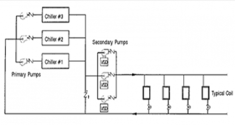
1) Primary Secondary water flow System –
It involves two sets of pumps, primary pumps and secondary pumps.
- Primary pumps are located before the chiller to maintain constant chilled water flow through chiller.
- Secondary pumps controlled through VFD and respective instruments which controls chilled water flow as per the system cooling requirement and it is located before the AHU.
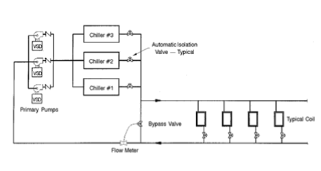
2) Variable Primary water Flow system –
In the Variable primary water flow system, only one set of pumps is used which are located before the chiller and it is equipped with VFD.
Example of Working of Variable Primary Chilled Water Flow System –
In this system, following components are used to control the flow –
- Differential Pressure Transmitter (DPT)
- Flow Meter
- Pumps with VFD
- Thermostat
- Two Way valves
When the system runs at its full load then all the three chillers run at its rated capacity. Thermostat is located inside the conditioned space / room, when the cooling load is reduced and inside area temperature reaches to the set point then the thermostat sends a signal to the 2-way control valve to reduce water flow rate to some extent.
Hence there is some pressure differential created between the chilled water header which will be transmitted by the Differential Pressure Transmitter (DPT). Then DPT sends a signal to the VFD of the pump to reduce its speed.
As per the chiller logic control, the automatic isolation valve operates the no. of chiller working in the part load conditions. There is one Bypass valve and Flow meter used in the system. As per the chiller selection, it needs a minimum amount of chilled water flow across it. As the cooling load reduced, respective chilled water flow requirement to cater that cooling load is less than the minimum chilled water flow requirement of the chiller, during that condition bypass valve and flow transmitter came in scenario. Flow transmitter senses the flow and sends the signal to the bypass valve to maintain the minimum chilled water flow across the chiller.
Location of Electric Equipment in the system –
- DPT – located between the supply and return line across the Air Handling Unit (AHU).
- Flow meter / transmitter – mounted in the return side of chiller.
- Pumps with VFD – These pumps are located before the chiller and they are operated with the help of VFD.
- Thermostat – It is located inside the air-conditioned area.
- Two Way valves – It is located in the return side of the chilled water side of AHU.
Advantages of Variable Primary Chilled Water Flow –
- Lower first cost - This is due to the elimination of the secondary pumps and associated fittings, vibration isolators, starters, power wiring, controls, etc. These savings are partly offset by higher costs of variable speed drives for the p-only system and the cost of the bypass valve and associated controls.
- Less Space Required- Due to the elimination of secondary pumps there are substantial cost reductions, depending on the plant layout and space constraints.
- Reduced pump design motor power requirement and size - There are two reasons for this reduction. First, the additional fittings and devices (shut-off valves, strainers, suction diffusers, check valves, headers, etc.) required for the secondary pumps are eliminated. Second, in most cases, average pump efficiency is also higher with the p-only system because primary pumps in the p-s system are usually high flow, low head pumps that are inherently less efficient unless pumps are oversized with low speed (e.g., 1,200 rpm) motors.

